First, the wind sent chute Overview:
Wind sent chute is a widely used transport dried powder materials pneumatic conveying equipment, also known as air transportation equipment, the wind sent the chute is made up of several cast plate cast trough connected together and arranged along the conveying direction into a certain slope. Upper and lower casings air layer is sandwiched in the middle trough.
Transportation of materials from the upper end of the housing feeding compressed air blown by the tone of the blower housing and through the dense lower porosity permeability layer between the material particles awarded the material is oxidized to change the so-called friction angle of the material to form a flow along the slope of the decline in the state to achieve the purpose of transportation. In the cement industry often used to transport water content ≤1%, temperature ≤150 ℃ cement and biological material. Air transport ramp worse applies to bauxite, transporting coal, ash, alumina, gypsum, flour, cement, phosphate powder easy flow of powder materials, high moisture content, poor performance fluidization materials should not be used.
Second, the wind sent chute features:
Chute no rotating parts in the transportation process, with its same function belt conveyor, screw conveyor, buried scraper conveyor compared with a easy to maintain, good sealing, no noise, safe and reliable operation, low energy consumption, easy change the conveying direction, and can do more feed unloading. The tank at high pressure centrifugal fan (9-19: 9-26 type) as the power source, so that the material in the custody transfer chute to maintain fluidization to tilt down one end can slow the flow. Wind sent the main part of the chute without transmission parts, to facilitate the sealing operation management, equipment, light weight, low power consumption, large transmission capacity, easy to change the conveying direction, using new breathable layer.
Third, the wind sent chute main structure:
Mainly from the feed chute opening, standard slots, non-tank, the shutoff valve (discharge valve), 3-90 ° curved grooves, cut valve, three slots, four slots, viewer, blowers, rain cover , the material downpipe, feed apron, breathable layer, conduits and other components.
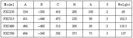
Fourth, the wind sent chute technical parameters:
Model |
FXC200 |
FXC250 |
FXC315 |
400 |
FXC500 |
FXC630 |
FXC800 |
The width of the groove |
200 |
250 |
315 |
400 |
500 |
630 |
800 |
Transmission capacity
t/h |
α=4° |
Cement |
22 |
40 |
70 |
130 |
220 |
320 |
400 |
Raw material |
16 |
30 |
55 |
100 |
165 |
245 |
310 |
α=6° |
Cement |
40 |
65 |
120 |
250 |
400 |
610 |
765 |
Raw material |
30 |
55 |
90 |
185 |
300 |
455 |
565 |
α=8° |
Cement |
50 |
80 |
140 |
300 |
470 |
720 |
900 |
Raw material |
35 |
65 |
110 |
225 |
355 |
540 |
670 |
α=10° |
Cement |
60 |
100 |
170 |
380 |
570 |
900 |
1080 |
Raw material |
45 |
80 |
140 |
285 |
425 |
670 |
800 |
α=12° |
Cement |
70 |
120 |
205 |
455 |
685 |
1080 |
1295 |
Raw material |
50 |
95 |
165 |
340 |
510 |
805 |
900 |
Tank section length/mm |
Standard section |
2000 |
Non-standard section |
250*n(n=1,2,3,4,5,6,7) |
Need pressure Kpa |
4~5.5 |
Required amount of wind( m³/㎡·min) |
1.5~2 |
Breathable layer |
Material |
Synthetic fiber |
Thickness mm |
4~6 |
Temperature ℃ |
150 |
Radial breaking strength N/cm width |
4700 |
Resistance Pa |
800~1200( In 2m³/㎡ · min condition) |
Fifth, the wind sent the chute standard tank Dimensions:
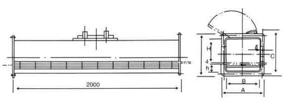
Wind sent chute standard slot Dimensions:
Sixth, the wind sent the chute works:
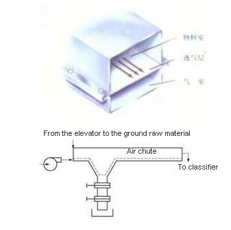
Its breathable layer material selection PET5 ~ 6. The above gas-permeable layer is feed chamber, below the air chamber, when gas is blown into the air with a certain pressure chamber, the material fluidized by the gas-permeable layer, and therefore the material under gravity like a fluid in the tank body flows, typically by centrifugation wind turbine as the source material excess indoor air through the exhaust port of the dust chute pumped.
Seven wind sent chute installation conditions:
1, the general linear conveyor installation access to material downward 6-10 degrees, up and down the tank and each tank to achieve convergence at the practical and reliable seal (which can be padded);
2, turn 90 degree bend (left and right);
3, tee slot or four-way bifurcation slot and, after the bifurcation load valve. In order to control the flow of fluidized material to ensure materials "allows gas" with the wind, the disabled segment can reduce the amount of wind-consuming;
4, under the tank conveyor line is too long or bifurcation plus side after the fan;
Air consumption is calculated:
V = 60 × α × (B / 1000) × L
Where V- air consumption m3 / h
α- air consumption per unit area of gas-permeable layer is generally 2.0--3m3 / m2 min;
B- chute Width mm;
L- chute length m.
5, the exhaust chute in the discharge chute on the tank exhaust, exhaust pipe should go after the small dust bag mouth, the air volume is 1.5 times the required amount of wind, air vents at the tank pressure required to maintain at 0 around.
Eight, use and maintenance of wind sent the chute:
1, first open the boot plus fans expected, the first stop feeding shutdown, to be expected while stocks (stocks at or near) before stopping fans, fan on when the bifurcation without downtime;
2, the trough should remain sealed, if any leakage, leaking powder should overhaul;
3. Replace the polyester breathable layer:
a, cutting, according to the requirements of the size of the gas-permeable layer good crop, with iron (or heating of steel bars) heating the incision blockade to prevent the spread;
b, perforated, with slightly less than the diameter of the mounting bolts of iron heating, air-permeable layer needs around the perforated portion of perforation. Pay attention not to let the fire burn perforated breathable layer. If the drilling rig, the rig to use hot iron after iron hot-week blockade of the hole to prevent raveling
c, the gas-permeable layer on the red tile in the box, through the bolt, surrounded with iron bars pressed to tighten the screw can be used to take;
d, layering (or flange) should go stab, weld grinding dry;
e, in order to ensure sealing, can be applied around the lower surface of the gas permeable layer polymer sealant (or plus 10 mm thick felt pad). |